Organised by Professor Cosmin Chiorean, Romania
3:45 - 4:00pm
The Hammock-Cost technique [1] is a project management technique based on the concept of Hammock activity. A Hammock activity is an activity that is scheduled between “regular” activities, since its duration cannot be estimated or calculated at the initial stage of project planning. Since a Hammock activity has the same starting and ending points similar to a standard project, a Hammock activity should be considered itself as a project, except that there is no significance in the order between its inner activities (meaning that, in principle, they may take place in parallel).A real-life example of using hammocks [2] refers to a huge project, the Westerscheldetunnel project. This complex project was divided into four Hammock activities, saving close to one billion Euros.
EFL (Embedded Flexible Language) is based on the Flexible Algorithms (FAs) [3-5] approach to parallel programming and computation. The FAs approach ensures well-defined deterministic parallel, and unordered sequential, execution. The programming and execution models of EFL are described in [3]. EFL was designed to encourage programmers to develop their computational thinking capabilities towards FAs, which actually are a kind of abstraction of sequential and parallel programming, all together. EFL was designed to allow the embedding of parallel code blocks into a sequential host language program.
Our target is to reduce the time complexity in complex software projects. In order to reach that target we developed the EFL-Hammock methodology which is based on the idea of combining the Hammock-Cost technique with EFL which is used as the implementation tool of a Hammock-based project.
We used the DEEPSAM algorithm [12] as a testbed upon which the EFL-Hammock methodology was tested. DEEPSAM [12] is a hybrid evolutionary programming (EP) algorithm for protein structure prediction. Like every evolutionary algorithm, DEEPSAM is composed by the following steps: (1) initial population creation, (2) the evolutionary loop, and (3) the local optimization of the population of the best solutions found during the evolutionary loop. T
DEEPSAM was designed and implemented before we developed our EFL-Hammock methodology. If we analyze DEEPSAM's architecture through the lens of the Hammock technique it is clear that we may say that it is a Hammock-based algorithm. Actually, the body of the DEEPSAM's loop is a Hammock composed by N Hammocks, each composed by N activities which are the application of N randomly chosen DEMSA operators upon the same data instance which is the same "parent" bio-molecular structure; actually, those N DEMSA operators are applied upon N replicas of the same "parent" data instance. This means that the architecture of the DEEPSAM's loop is composed by two layers of Hammocks. It may be seen that the behavior of the DEEPSAM algorithm, as explained above, reminds in some way the behavior of the REMD algorithm [12].
Note that if the EFL-Hammock methodology was in existence when DEEPSAM was designed and implemented it could be built in a more systematic way. Thus, based on those observations about the Hammock-based architecture of DEEPSAM, we decided to use it as a testbed for the EFL-Hammock methodology.
DEEPSAM may be run according to four alternative run modes: serial, parallel, serialparallel, and parallelserial. Let's analyze those four run modes from a Hammock-based point of view:
DEEPSAM was run upon two bio-molecules: Met-Enkephalin (pdb code 2LWC) which is a 5-aminoacid-long peptide and Cysteine Deleted Protegrin-1 (pdb code 2MQ5) which is a 10-aminoacid-long peptide. The computer used for our run experiments is composed by 24 Intel-Xeon processors with 13Gb RAM, running under the Linux Operating System.
DEEPSAM was run for 1,2,4,6,8,15,20, and 30 iterations in its four run modes:
Nr of Iterations | |||||||
20 | serial | 8106.817911 | 405.3408955 | 8459.824257 | 231.20588 | ||
20 | serialparallel | 2429.924012 | 121.4962006 | 2555.403336 | 59.264706 | ||
20 | parallelserial | 2576.722169 | 128.8361084 | 2806.790626 | 67.555556 | ||
20 | parallel | 1165.308029 | 58.26540145 | 1413.199094 | 20.794118 | ||
Nr of Iterations | |||||||
30 | serial | 13877.22941 | 462.5743136 | 14507.73221 | 270.68 | ||
30 | serialparallel | 3396.323817 | 113.2107939 | 3426.47853 | 48.130435 | ||
30 | parallelserial | 4476.824142 | 149.2274714 | 4629.285847 | 74.6875 | ||
30 | parallel | 1812.032387 | 60.40107957 | 2046.010096 | 20 | ||
general avg of full loop runtime | general avg iteration runtime | general avg runtime of all the usepop step of DEEPSAM runs | general avg pardemsa runtime | ||||
serial | 4539.025222 | 348.0037092 | 5144.434747 | 253.36254 | |||
serialparallel | 1146.188311 | 82.56408249 | 1264.856909 | 54.097269 | |||
parallelserial | 1442.323604 | 103.0469213 | 1600.572153 | 67.517361 | |||
parallel | 598.9655496 | 32.31058376 | 630.1800603 | 17.327687 |
From that data it is clear that our experiments corroborate our intuition that the serialparallel and parallelserial run modes, are those that we would advise to use in projects' development because of their better agreement with the principles of the Hammock-Cost approach , and are relatively efficient in their use of computational resources (CPU time and main memor).
References
I
In this paper we presented the principles of the EFL-Hammock methodology, a new project development and management methodology. The combination of EFL and Hammock -cost technique is fruitfull in computing applications. In this new att As our first intuition,serialparallel and parallelserial run modes output the best results.
4:00 - 4:15pm
In steel structural system analysis some factors, such as geometric imperfections, material nonlinearity and semi-rigid connections, can contribute to the reduction of the structural system bearing capacity.
In the numerical context, there are several researches that deal with the semi-rigid joints and plastification of steel structures (Chan & Chui, 2000; Lemes et al., 2017). To describe the connections behavior, it is common to use zero-length rotational pseudo-springs at the finite elements ends. The Refined Plastic Hinge Method (RPHM) has emerged as a fast and accurate option for structural plastification simulation. Lemes et al. (2017) developed an alignment of the Strain Compatibility Method (SCM) with the RPHM producing reliable results in the analysis of steel, reinforced concrete and steel-concrete composite structures. Another important factor in the steel plasticity analysis is the residual stresses.
The objective of the present work is to promote the use of the SCM/RPHM with the pseudo-springs at the finite elements ends, representing the beam-to-column connections, in the steel structures systems modeling. Some results are illustrated for validation of the proposed methodology.
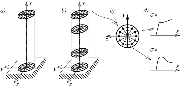
In the model of the structural systems using co-rotational-FE, the beam-column finite element is used, defined by nodes i and j, as shown in Fig. 1. The finite element equilibrium, in incremental form, is given by:
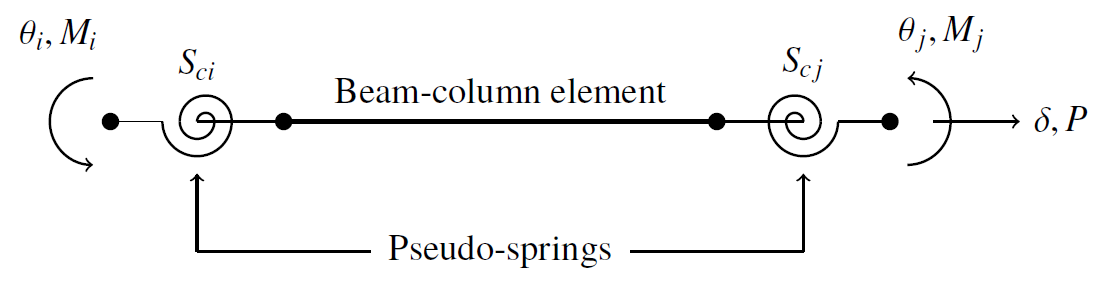
Figure 1: Co-rotational hybrid beam-column finite element
(1) |
with β = (Sci + k22) (Scj + k33) - k23 k32. ΔP, ΔMci and ΔMcj are the axial force and bending moments increments; Δδ, Δθci and Δθcj are the axial displacement and nodal rotations increments, respectively; and Sc is the spring rotational stiffness parameter. The coefficients kij of the stiffness matrix may be modified adding the geometric nonlinearity consideration, which are introduced in this methodology by the nonlinear formulation proposed by Yang and Kuo (1994).
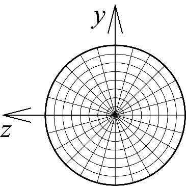
The axial and flexural stiffnesses are introduced in this formulation by the Strain Compatibility Method (SCM) (Chiorean, 2013). Thus, the moment-curvature behavior of the section is determined by the application of the standard Newton-Raphson nonlinear solution to cross sections equilibrium problem. Thus, the cross-section constitutive matrix is given by:
| (2) |
where Nint and Mint are the axial and flexural internal forces; and ε0, Φ are the axial strain and curvature of the section.
The full yield curves are obtained before the structural analysis (out of incremental cycle). This strategy is adopted to reduce the time of the numerical simulations.
When the section plastify, any increase in incremental load causes the internal forces to extrapolate the full yield curve, therefore, violating the cross-section bearing capacity. The formulation used here avoiding this violation is a strategy known as return mapping. In this strategy, the element axial force remains constant and the internal bending moment returns to the full yield curve.
The six storey steel frame showed in Fig. 2 was initially studied by Vogel (1985) considering both distributed and concentrated plasticity. The geometry, cross-sections, loads and the used finite element mesh are represented in the same figure. All the loads are incremental. The structure has a global geometric imperfection equal to 1/450.
The steel section has yield stress equal to 235 MPa and a modulus of elasticity taken as 205 GPa. The study adopted an elastic-perfectly-plastic relationship without material strain hardening. Chan & Chui (2000) proposed a numerical study of this structural system considering the semi-rigid connections.
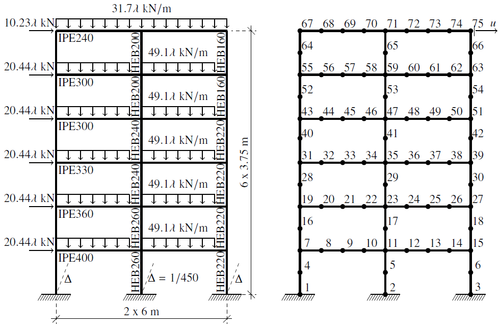
Figure 2: Six-storey two-bay frame: geometry, loads and adopted FE mesh
The semi-rigid connections are tested considering the linear and nonlinear behavior of the four exponential connections models described above. For simulating the joint linear behavior, the parameter Sc is kept constant and its value is taken directly from the exponential model is used (Chan & Chui, 2000). The load-displacement curves for the four analyses performed are shown in Figs. 3 and 4.
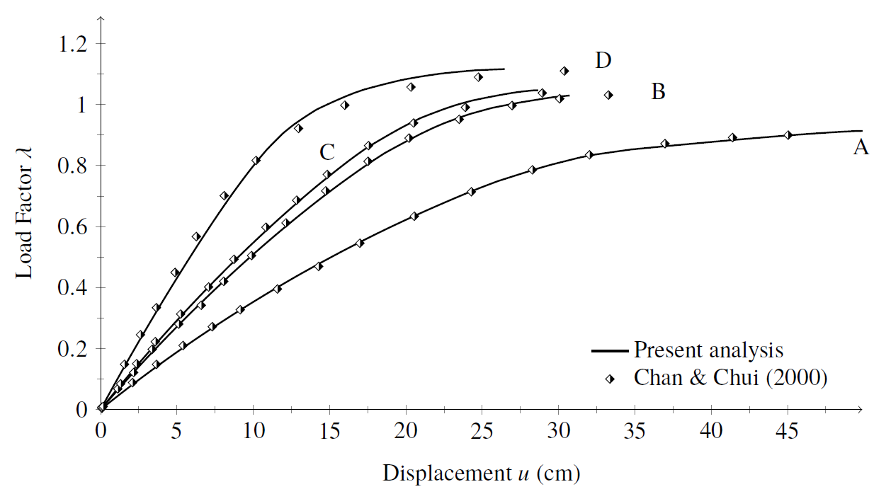
Figure 3: Vogel steel frame: equilibrium paths using linear joint model
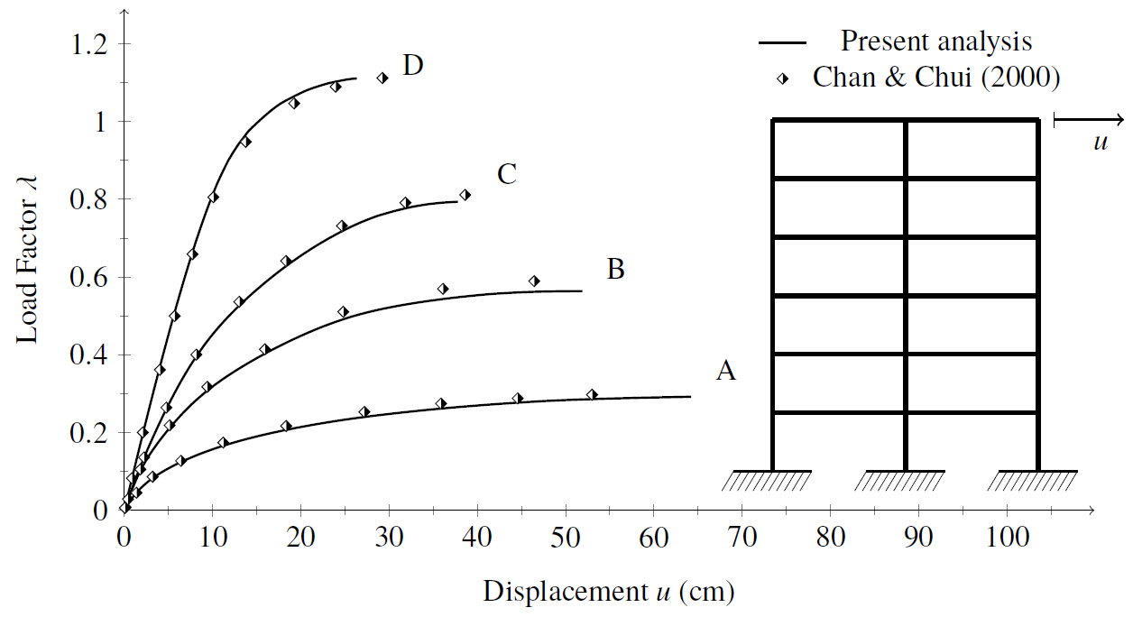
Figure 4: Vogel steel frame: equilibrium paths using nonlinear joint model
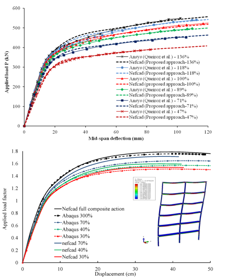
The equilibrium paths clearly demonstrate the bearing capacity variation and the structural system stiffness change as each of the four connections models are simulated. It is worth highlighting that, when adopting the nonlinear joint model, the system bearing capacity reduction using the single web angle connection (type A) is approximately 73.5% smaller than the system with extended end plate connections (type D).
In the numerical simulations with linear joint models, higher critical loads were obtained than using the nonlinear models. In fact, keeping the parameter Sc as a constant induces a more rigid system, implying smaller displacements and internal forces due to geometric nonlinearity. Moreover, when using the linear models the connection ultimate moment is not reached and the cross-section bearing capacity governs the structural system behavior.
Using the exponential model, one can clearly see a critical load reduction in a more accentuated way than using linear models for the curve M-ϕ description. Going further, one realizes that the more rigid connection, there is greater influence of the material nonlinearity. In the simulation using the D-type connection, there are 16 plastic hinges formed in addition to 43 other sections in the flexural stiffness degradation process. These numbers reduced to 1 formed plastic hinge and 39 sections degrading for analysis with type C connection. The results obtained with the semi-rigid connections B and A presented no plastic hinge formation, only partial degradation in 18 and 7 sections, respectively.
This work presented a numerical formulation based on the concentrated plasticity concept and semi-rigid joints to evaluate the steel frames nonlinear behavior. For this, a hybrid finite element with rotational pseudo-springs was used. These springs were added to the finite element previously developed Lemes et al. (2017) for the simulation of the connections nonlinear behavior.
In the presented example, the good accuracy of the proposed methodology was verified when compared to the literature results. The variations in the beam-to-column connections models showed the strong influence on the global structural system behavior as well as the influence of the joint type on the inelastic behavior of the structure members. For analysis of other connection types not represented by exponential model, one can use the multilinear model for the moment-rotation relation description. In this model, the M-ϕ curve is described through a series of linear stretches that may represent any connection behavior.
Acknowledgments
The authors would like to thank CAPES, CNPq, FAPEMIG and UFOP/PROPP for the financial support received. Special thanks to Professor Péter Z. Berke from ULB for his hospitality during the manuscript’s review at Batir.
REFERENCES
CHAN, S. L.; CHUI, P. Non-linear static an cyclic analysis of steel frames with semi-rigid connections. Oxford: Elsevier, 2000.
CHIOREAN, C. G. A computer method for nonlinear inelastic analysis of 3D composite steel-concrete frame structures. Engineering Structures, v. 57, p. 125–152, 2013.
ECCS. Ultimate limit state calculation of sway frames with rigid joints. European Convention for Constructional Steelwork, Pub. no. 33, 1983.
LEMES, Í.J.M.; SILVEIRA, R.A.M.; SILVA, A.R.D.; ROCHA, P.A.S. Nonlinear analysis of two-dimensional steel, reinforced concrete and composite steel-concrete structures via coupling SCM/RPHM. Engineering Structures, v. 147, p. 12-26, 2017.
VOGEL, U. Calibrating frames. Stahlbau. Berlim, 1985.
YANG, Y.; KUO, S. Theory & analysis of nonlinear framed structures: Prentice Hall, 1994.
This work presents a numerical methodology based on Euler-Bernoulli theory to analyze the nonlinear behavior of steel planar structures. The displacement-based formulation uses the Refined Plastic Hinge Method (RPHM) principles to simulate the concentrated plasticity at the co-rotational finite element nodal points. To present a more realistic simulation of the axial and flexural stiffness degradation, the RPHM is coupled to the Strain Compatibility Method (SCM), where the materials constitutive relations are explicitly used. The SCM is also applied in determining the structural elements bearing capacity. Residual stress models are addressed and introduced explicitly in subareas of steel sections generated by a two-dimensional cross-sectional discretization. The semi-rigid connections are simulated by the rotational pseudo-springs at the finite elements ends, and the connection behavior is given by its moment-rotation relation. The presented numerical formulation results are consistent with the classical experimental and numerical literature responses
4:15 - 4:30pm
In recent years, have witnessed significant advances in nonlinear inelastic analysis methods for composite steel-concrete beams and framed structures and integrate them into the new and more rational advanced analysis and design procedures. Currently the available tools for such analysis are general purpose FE programs that require extensive calibration and mesh generation studies and still possess huge demands on the most powerful of available computers and represents unpractical tasks for structural engineer [1]. In this paper, a novel second-order inelastic flexibility-based element has been developed by combining the Maxwell-Mohr rule and the second-order force based functions for computation of the incremental force-displacement relationships at the element level. The proposed model allows explicit and efficient modelling of the initial geometric imperfections and residual stresses and is intended to model the combined effects of nonlinear geometrical effects, gradual spread-of-plasticity, partial shear connection of composite beams, finite-size joints and nonlinear behaviour of semi-rigid connections by using only one 2-noded (12 DOF) beam-column element per physical member. Based on elasto-plastic cross sectional analyses the behaviour model accounts for the effects of partial composite action between the concrete slab and the steel beam. Gradual yielding throughout the cross-section is described through basic equilibrium, compatibility, material and shear connection nonlinear constitutive equations. Using an updated Lagrangian formulation, the global geometrical effects are considered, updating the element forces, member lengths and the rotation matrix corresponding to transformations equations from local to global coordinates, at each load increment. A predictor/corrector strategy has been implemented, corresponding to the proposed flexibility-based element, in order to find the nodal displacements and the element resisting forces. The proposed model has been implemented in an incremental-iterative structural analysis program (NEFCAD) and has been verified by comparing the predicted results with the established results available from the literature.
Within the framework of flexibility-based formulation a 2-noded 3D frame element able to take into account the distributed plasticity, partial composite action in the case of composite beams and nonlinear behaviour of semi-rigid connections is developed. The nonlinear effects of partial composite action between the reinforced concrete slab and the steel beam are taken into account innovatively by introducing the internal axial force of the concrete slab as function of the member effective degree of composite action, hence, the inelastic cross-sectional response can be formulated by means of three equilibrium equations [2]. Both uniform and non-uniform distribution of the shear connectors can be efficiently considered in the proposed formulation.
The composite columns are modelled as composite sections with full composite action subjected to bi-axial bending and axial force. The gradual yielding throughout the cross-section is described through basic equilibrium, compatibility, material and shear connection nonlinear constitutive equations, the states of strain, stress and yield stress are monitored explicitly during each step of the analysis and then tangent flexural and axial rigidity of the cross section are derived. At this level the proposed method addresses computational efficiency through the use of path integral approach to numerical integration of the cross-sectional nonlinear characteristics.
The incremental force-displacement relationships at the element level are derived directly from energetic principles, by applying the Maxwell-Mohr rule for computation of generalized displacements in the second-order geometrically nonlinear analysis. In this respect the element force fields are described by the second-order bending moments and shear forces derived by solving the second-order differential equilibrium equation expressing the variation of the bending moment along the member length in the presence of the compressive axial force, member lateral loads and the second-order effects associated with the initial geometric imperfections.
The behaviour of the connection element in each principal bending direction is represented by a rotational dimensionless spring attached to the member ends.
A computer program, NEFCAD, has been developed to study the combined effects of material, geometric and semi-rigid connections nonlinear behaviour for planar and spatial composite steel-concrete framed structures. Within the framework of updated Lagrangian formulation (UL) and in the incremental-iterative approach adopted, at each load increment, a modified constant arc-length method is applied to compute the complete nonlinear load-deformation path. Two computational examples are given to validate the accuracy and efficiency of the proposed method. In the present approach, one element has been used to model each column and beam in all computational examples. The advanced numerical simulation is conducted here by using the specialized software for nonlinear analysis of structures, ABAQUS v. 6.11 [3].
Figure 1. Load-deflection curves. a. Simply supported composite beam. b. Six-story composite frame
Figure 1a presents the comparative load-deflection curves for simply supported E1 composite beam tested by Chapman & Balakrishnan [4], obtained with the proposed approach as well as against the results predicted by Queiroz et al (2007) [5] using the more complex finite element analysis software Ansys, when different degrees of shear connections are taken into account. Comparing the curves depicted in Figure 1a, it can be observed, that the proposed method (Nefcad) predicts fairly well the nonlinear behaviour and ultimate load capacity of the system when different levels (ranging from 47% to 136%) of shear connection are considered. Figure 1b depicts the load deflection curves for a six story composite frame, predicted by the proposed approach considering different degrees of shear connection, and those obtained with more complex finite element analysis (Abaqus). It can be seen that the present method predicts fairly well the nonlinear behaviour and ultimate load capacity.
A reliable and robust nonlinear inelastic analysis method for 3D composite steel-concrete frames with partial composite action and semi-rigid connections has been developed. The concept of the inelastic member effective degree of composite action has been introduced and an efficient nonlinear inelastic analysis method for composite steel-concrete beams that is able to take into account the combined effects of distributed plasticity and partial composite action between the concrete slab and the steel beam has been developed. A novel second-order inelastic flexibility-based element has been developed. A predictor/corrector strategy has been implemented, corresponding to the proposed flexibility-based element. The proposed formulation takes advantage of using only one 2-noded beam-column element and features, in this way, the ability to be used for practical applications. The accuracy of the analytic procedure and the computer program developed here, has been evaluated using several benchmark problems, by comparing the results with experimental data, advanced three-dimensional FEM model developed by the authors in Abaqus software package and other results reported by researchers using independent finite element solutions. It can be concluded that the global behaviour of frame structures with partial composite action, both in elastic and post-elastic field as well as the ultimate loading capacity predicted by the proposed approach, correlate reasonable well with the experimental results and advanced finite element models.
References
1. Chiorean C.G., “A computer method for nonlinear inelastic analysis of 3D composite steel-concrete frame structures”, Eng Struct, 57, 125-152, 2013
2. Chiorean C.G. and Buru S.M., “Practical nonlinear inelastic analysis method of composite Steel-concrete beams with partial composite action”, Eng Struct, 134, 74-106, 2017.
3. Abaqus - User’s Manual. Hibbit, Karlsson & Sorenson, 2011.
4. Chapman J.C. and Balakrishnan S., “Experiments on composite beams”, The Structural Engineer, 42, 369-383, 1964.
5. F.D. Queiroz, P.C.G.S. Vellasco, D.A. Nethercot "Finite element modelling of composite beams with full and partial shear connection", J Constr Steel Res, 63, 505-521, 2007.
This paper presents an efficient computer method for large deflection distributed plasticity analysis of 3D semi-rigid composite steel-concrete frameworks. A novel second-order inelastic flexibility-based element has been developed by combining the Maxwell-Mohr rule and the second-order force based functions for computation of the generalized displacements. The proposed model allows explicit and efficient modeling of the combined effects of nonlinear geometrical effects, gradual spread-of-plasticity, partial shear connection of composite beams, finite-size joints and joint flexibility by using only one 2-noded beam-column element per physical member. For composite beams, based on elasto-plastic cross-sectional analyses the model is able to take into account the effects of partial composite action between the concrete slab and the steel beam. Both uniform and non-uniform distribution of the shear connectors can be efficiently considered in the proposed formulation.
The proposed approach implies an explicit solution of the second-order differential equilibrium equation of the composite beam with partial composite action in which the axial force in the concrete slab represents the main unknown. The axial force in the concrete slab, the solution of the differential equilibrium equation, can be expressed in function of the axial force under the assumption of the full composite action multiplied with a function of the degree of composite action which include also the exact distribution of the bending moment along the member length. By simply dividing the beam according with the variable distribution of shear connectors and solving the second-order differential equilibrium equations for each segment considered as beams with uniform distribution of shear connectors, and then imposing the boundary and continuity conditions represents a direct and simple way to treat the cases of non-uniform distribution of shear connection along the beam length. At the cross sectional level the proposed method addresses computational efficiency through the use of path integral approach to numerical integration of the cross-sectional nonlinear characteristics and residual stresses, enabling in this way the accurate geometrical specifications and precise modeling of cross-sections.
The proposed nonlinear analysis formulation has been implemented in a general nonlinear static purpose computer program, NEFCAD. Several computational examples are given to validate the accuracy and efficiency of the proposed method.
4:30 - 4:45pm
Fiber beam/column elements are widely used in nonlinear frame analysis. One variant of these elements are the fiber hinge models with monitored fiber sections at each element end and a linear elastic part in between (Figure 1). Another variant are distributed inelasticity fiber beam/column elements with several sections over the element length, so that inelastic deformations are monitored at any of these locations. In fiber beam/column elements, the cross section is discretized into several integration points (fibers) and the cross section integration is performed numerically through summation over all fibers [1].
Figure 1. a) Fiber hinge element, b) distributed plasticity fiber beam-column element,
c) cross-section discretization and d) assigned uniaxial material models
The numerical accuracy and computational efficiency of the fiber elements depends on the number of monitored cross sections and is directly related to the cross section discretization and the integration rule [2]. This study is the extension of the earlier study by Kostic and Filippou [2] related to the section discretization problem of steel wide-flange and rectangular reinforced concrete cross-sections. In this study, the third most common cross-section type, the circular section, is analyzed. One of the conclusions of the previous study is that higher order integration rules do not offer benefits over the midpoint integration rule under cyclic loading with large inelastic strains. This study is, therefore, focused on discretizations based on the midpoint integration rule.
The fiber discretization of the circular cross-section is commonly defined through two parameters: nr and nth. The first parameter nr represents the number of subdivisions in the radial direction, while nth represents the number of subdivisions in the circumferential direction. The resulting section discretization is shown in Figure 2. Unfortunately, this discretization has a disadvantage that many small-area fibers are located near the center of the cross-section, while it is the fiber farthest form the center that experience inelastic strains and contribute most to the flexural response. Consequently, this type of discretization is not optimal for nonlinear section analysis.
Figure 2. Common discretization of circular cross-section
For these reasons, this study focuses on alternative cross-section discretization schemes. Besides the “standard” discretization scheme in Figure 2, which is subsequently called “Midpoint 1” scheme, two alternative discretizations are evaluated:
Figure 3 shows all discretization schemes for a homogeneous circular section and nr =4.
Figure 3. Discretization schemes for circular cross-section
With these discretization schemes, the following four types of cross-sections are analysed (Figure 4):
Figure 4. Analyzed circular cross-section
The four cross-sections from Figure 4 are subjected to 10 different loading protocols with different section discretizations, in order to cover the wide range of numerical situations that may occur during the time history analysis of a structural member. The loading protocols are are schematically shown in Figure 5. Tests 6 to 10 have the same displacement patterns as tests 1-5, but with variable axial force.
Figure 5. Analyzed loading protocols
For the four cross sections under study, the following material models are used. The homogeneous circular section is modeled with the bilinear hysteretic material model with hardening; In RC, CRC and CFT sections, the concrete is modeled with the Mander model [3], without concrete tensile strength, while the steel and reinforcement steel are modeled with the bilinear hysteretic material model with hardening.
For each of these discretizations and each loading protocol, the error is calculated by comparing the energy dissipation under complex cyclic inelastic response [2]. This error measure takes into account all stress resultants and the corresponding deformations.
From the results of the extensive set of cyclic numerical tests, the following conclusions are derived:
It is shown that the errors for the global (displacements, drifts) and local response measures (curvatures, strains) for the whole structure are smaller.
New discretization schemes for circular cross-sections are computationally very efficient, but also highly accurate. Therefore, they are suitable for nonlinear fiber section (element) analysis. With the proposed schemes, significant savings in computational time can be achieved in comparison with the standard discretization scheme.
Acknowledgment: The first author thanks the Ministry of Science of the Republic of Serbia for financial support under the project number TR36046.
References:
In fiber beam/column elements, the cross section is discretized into several integration points (fibers) and the cross-section integration is performed numerically through summation over all fibers. This paper discusses the discretization of the circular section, which is a very common cross-section shape in civil engineering. This cross-section appears also in RC members and CFT columns. The new, computationally very efficient section discretization schemes, based on the simple midpoint integration rule, are presented. The accuracy of the schemes is evaluated on an extensive set of biaxial loading conditions with constant and variable axial load. It is shown that the new integration schemes are a better choice than standard section discretization schemes for circular cross-section. Practical recommendations for the discretization of this type of cross-section are derived.
4:45 - 5:00pm
Moment-curvature analysis and interaction diagrams of cross-sections are of prime importance in the analysis of inelastic behavior of heated cross-sections subjected to bi-axial loading and axial force. A complete moment-curvature relationship shows strength reduction beyond the peak point, when strain-softening exhibited by the concrete is taken into account, and degradation of flexural and axial rigidity of cross-section at different stages of loading and fire attacks. On the other hand, direct evaluation of the interaction diagrams or moment capacity contour is of prime importance for rapid and practical design of composite steel-concrete cross-sections. Some analytical studies and numerical procedures based on deformation (i.e. curvature) driven algorithms on the moment-curvature responses are available in literature. Such approaches exhibits relatively well numerical stability but the main drawback of these approaches is given by the fact that, for arbitrary shape cross-section, the resulted bending moments associated to the prescribed total curvature do not laying in the same plane. Several studies may be found in the international literature concerning the interaction diagrams evaluation of composite steel-concrete cross-sections at elevated temperatures [1-4]. However, only few studies have been focused on the general cases of bi-axial bending loading and most of them generate the failure surface through three-dimensional curves making the application of these techniques rather cumbersome for practical applications. In this work the complete moment-curvature diagrams are determined such that axial force and bending moment ratio is kept constant. In this respect a strain-driven algorithm has been developed. The ultimate strength capacity is formulated as a problem of unconstrained mathematical optimization by applying the method of Lagrange multipliers.
The analysis methods are carried out in two main steps: (i) thermal analysis, used to evaluate the temperature distribution throughout the cross-section and (ii) mechanical analysis, in which moment-curvature and interaction diagrams are determined.
The main feature of the proposed moment-curvature approach consists in controlling the inelastic response at the strains level enforcing in the same time the elato-pastic equilibrium for a prescribed axial force and bending moments ratio. Such an approach allows a very precise evaluation of the strain and stress state throughout the arbitrary shaped cross-section allowing direct evaluation of the inelastic curvatures from a prescribed value of the strain in the farthest point (concrete fibre) from the neutral axis along the boundary of the cross-section. In the proposed approach the Newton iterative strategy is applied only to two coupled nonlinear equilibrium equations, enforcing in the same time equilibrium for bending moments about each principal axis.
Ultimate strength capacity of a cross-section subjected to bi-axial bending moments and axial force is defined as maximum values of the bending moments under constant axial force associated to a specific deformed state when further increase in deformation results in reduced response. On the other hand, the nominal strength capacity of the cross-section is reached when in the most compressed concrete fibre or tensioned steel the predefined nominal ultimate values of the strains are attained. In general, conventional (nominal) strength capacity occurs prior to maximum (ultimate) strength capacity when considering material standard laws without strain-softening branches.
A new direct numerical procedure is proposed herein in order to determine the ultimate strength capacity of composite steel-concrete cross-sections with arbitrary shape at elevated temperatures. The ultimate (maximum) strength capacity is formulated as a problem of unconstrained mathematical optimization by applying the method of Lagrange multipliers for finding the local maxima of a function subjected to equality constraints. The optimized function is defined as a total internal bending moment and two constrains are defined by imposing the constant axial force and bending moment ratio. Both vertical and horizontal interaction diagrams are evaluated taking into account the material property degradation due to the temperature increase and the additional thermal strains under the assumption that spalling of concrete does not occur.
A computer program, ASEP, has been developed both for thermal and mechanical analysis. The accuracy and computational advantages of the numerical procedure developed here has been evaluated by using a selected benchmark problem [1]. An explicit numerical time integration strategy based on the finite difference method is adopted, in the developed computer program, to obtain the temperature distribution at the cross-sectional level discretized into a mesh of three-node iso-parametric finite elements with three integration points. The temperature distribution is known throughout the mesh and then these values are used in fiber based inelastic strength analysis of cross-sections. Moisture effects, specific heat, thermal conductivity and density are considered according to Eurocode 2 for concrete with siliceous aggregate and 0% moisture. The stress-strain relation adopted for concrete and steel under high temperatures are taken from Eurocodes. The capacity diagrams are reported at the plastic centroid of the cross-section. The temperature fields for a 30, 90, 180 and 300 minutes exposure are depicted in Fig. 1. Caldas et al. 2010 studied this cross-section and nominal bending moment capacities have been determined associated to the ultimate compressive strain adopted conservatively as the value corresponding to the peak stress. As expected, higher exposure times leads to contraction of the moment capacity diagrams, this means lower strength capacity of cross-section. As it can be seen fairly good agreement exist between the results obtained from the proposed approach and those selected from literature. However, some differences can be observed between the predicted results using the proposed approach and those given in [1]. These differences can be attributed to the approaches involved in the computation of the capacity diagrams. The procedure developed in [1] determine the nominal strength capacity assuming lower limit strain for concrete (associated to the peak stress) whereas the proposed approach determine the ultimate strength capacity associated to the maximum total bending moment of the cross-section corresponding to a specific deformed state when further increase in deformation results in reduced response. Moreover, it is important to note that the methods reported in [1,4], used here for comparisons, does not generate genuinely plane moment capacity curves, as is the main feature of the proposed approach.
Figure1. Temperature distribution and moment capacity contours.
A new computational method for the ultimate strength and moment-curvature analysis of composite steel-concrete cross-sections with arbitrary shape subjected to elevated temperatures has been developed. Comparing the proposed method with the existing ones we may highlight several important features that make the proposed approach more numerically robustness and computational effective: this procedure adopts an explicit tangent stiffness strategy for the solution of the resulted nonlinear equilibrium equations thus resulting in a high rate of convergence and the ultimate strength capacity is direct evaluated by solving just three coupled nonlinear equations enforcing in the same time equilibrium for bending moments about each principal axis resulting genuinely plane interaction diagrams. The examples and the comparisons made prove the effectiveness and reliability of the proposed method of analysis.
References
1. Caldas, R.B., Sousa, J.B.M., Fakury, R.K. Interaction diagrams for reinforced concrete sections subjected to fire, Engineering Structures, 32, 2832-38, 2010.
2. El-Fitiany, S.F., Youssef, M.A. Interaction diagrams for fire-exposed reinforced concrete sections, Engineering Structures, 70, 246-259, 2014.
3. Law A. and Gillie M. Interaction diagrams for ambient and heated concrete sections, Engineering Structures, 32, 1641-49, 2010.
4. Chen, S.F., Teng, J.G., and Chan, S.L. Design of biaxially loaded short composite columns of arbitrary section, Journal of Structural Engineering, 127, 840-846, 2001.
This paper presents a new computational method for moment-curvature and ultimate strength analysis of composite steel-concrete cross-sections with arbitrary shape subjected to elevated temperatures. The analysis method is carried out in two main steps: (i) thermal analysis, used to evaluate the temperature distribution throughout the cross-section at a specific time and (ii) mechanical analysis, in which the interaction and moment-curvature diagrams are determined.
The main feature of the proposed approach consists in controlling the inelastic response at the strains level enforcing in the same time the elasto-plastic equilibrium for a prescribed axial force and bending moments ratio. The ultimate strength capacity is formulated as a problem of unconstrained mathematical optimization. The optimized function is defined as a total internal bending moment and two constrains are defined in terms of constant axial force and bending moment ratio. Applying the method of Lagrange multipliers for finding the local maxima of a function subjected to equality constraints the ultimate bending moment capacities are directly obtained by solving just three coupled nonlinear equations.
Comparing the proposed method with the existing ones several important features may be highlighted: (i) the proposed approach is able to compute the ultimate strength capacity of cross-sections directly, with a high degree of accuracy, without the need to evaluate the entire moment-curvature diagram, by means of solving just three coupled nonlinear equations enforcing in the same time equilibrium for bending moments about each principal axis resulting genuinely plane interaction diagrams; (ii) the numerical procedure adopted for solving the nonlinear system of equations involves a direct and explicit tangent stiffness strategy thus resulting in a high rate of convergence; (iii) from the extensive numerical experiments, some of them presented in this work, has been found that the convergence stability is not sensitive to the initial/starting values of the iterative process, to how the origin of the reference loading axes is chosen or to the strain softening exhibited by the concrete in compression. The developed procedure has been used to determine the bending moment capacity diagrams of composite-steel concrete cross-section with arbitrary shape and different fire exposure regimes. The comparisons made prove the effectiveness and reliability of the proposed method of analysis.
Further studies are envisaged for extending the proposed approach for nominal strength capacity evaluation and also studies concerning the numerical stability and computational efficiency of this approach are underway and will be presented in a future work.